


UART, Serial Port, RS-232 Interface
Code in both VHDL and Verilog for FPGA Implementation
Do you know how a UART works? If not, first brush up on the basics of UARTs before continuing on. Have you considered how you might sample data with an FPGA? Think about data coming into your FPGA. Data can arrive by itself or it can arrive with a clock. When it arrives with a clock, it is call synchronous. When it arrives without a clock, it is called asynchronous. A UART is an asynchronous interface.
In any asynchronous interface, the first thing you need to know is when in time you should sample (look at) the data. If you do not sample the data at the right time, you might see the wrong data. In order to receive your data correctly, the transmitter and receiver must agree on the baud rate. The baud rate is the rate at which the data is transmitted. For example, 9600 baud means 9600 bits per second. The code below uses a generic in VHDL or a parameter in Verilog to determine how many clock cycles there are in each bit. This is how the baud rate gets determined.
The FPGA is continuously sampling the line. Once it sees the line transition from high to low, it knows that a UART data word is coming. This first transition indicates the start bit. Once the beginning of the start bit is found, the FPGA waits for one half of a bit period. This ensures that the middle of the data bit gets sampled. From then on, the FPGA just needs to wait one bit period (as specified by the baud rate) and sample the rest of the data. The figure below shows how the UART receiver works inside of the FPGA. First a falling edge is detected on the serial data line. This represents the start bit. The FPGA then waits until the middle of the first data bit and samples the data. It does this for all eight data bits.
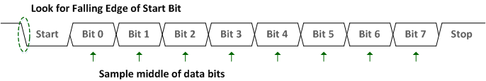
UART Serial Data Stream
The above data stream shows how the code below is structured. The code below uses one Start Bit, one Stop Bit, eight Data Bits, and no parity. Note that the transmitter modules below both have a signal o_tx_active. This is used to infer a tri-state buffer for half-duplex communication. It is up your specific project requirements if you want to create a half-duplex UART or a full-duplex UART. The code below will work for both!
If you want to simulate your code (and you should) you need to use a testbench. Luckily there is a test bench already created for you! This testbench below exercises both the Transmitter and the Receiver code. It is programmed to work at 115200 baud. Note that this test bench is for simulation only and can not be synthesized into functional FPGA code.
VHDL Implementation:
VHDL Receiver (UART_RX.vhd):
----------------------------------------------------------------------
-- File Downloaded from http://www.nandland.com
----------------------------------------------------------------------
-- This file contains the UART Receiver.  This receiver is able to
-- receive 8 bits of serial data, one start bit, one stop bit,
-- and no parity bit.  When receive is complete o_rx_dv will be
-- driven high for one clock cycle.
--
-- Set Generic g_CLKS_PER_BIT as follows:
-- g_CLKS_PER_BIT = (Frequency of i_Clk)/(Frequency of UART)
-- Example: 10 MHz Clock, 115200 baud UART
-- (10000000)/(115200) = 87
--
library ieee;
use ieee.std_logic_1164.ALL;
use ieee.numeric_std.all;

entity UART_RX is
  generic (
    g_CLKS_PER_BIT : integer := 115     -- Needs to be set correctly
    );
  port (
    i_Clk       : in  std_logic;
    i_RX_Serial : in  std_logic;
    o_RX_DV     : out std_logic;
    o_RX_Byte   : out std_logic_vector(7 downto 0)
    );
end UART_RX;


architecture rtl of UART_RX is

  type t_SM_Main is (s_Idle, s_RX_Start_Bit, s_RX_Data_Bits,
                     s_RX_Stop_Bit, s_Cleanup);
  signal r_SM_Main : t_SM_Main := s_Idle;

  signal r_RX_Data_R : std_logic := '0';
  signal r_RX_Data   : std_logic := '0';

  signal r_Clk_Count : integer range 0 to g_CLKS_PER_BIT-1 := 0;
  signal r_Bit_Index : integer range 0 to 7 := 0;  -- 8 Bits Total
  signal r_RX_Byte   : std_logic_vector(7 downto 0) := (others => '0');
  signal r_RX_DV     : std_logic := '0';

begin

  -- Purpose: Double-register the incoming data.
  -- This allows it to be used in the UART RX Clock Domain.
  -- (It removes problems caused by metastabiliy)
  p_SAMPLE : process (i_Clk)
  begin
    if rising_edge(i_Clk) then
      r_RX_Data_R <= i_RX_Serial;
      r_RX_Data   <= r_RX_Data_R;
    end if;
  end process p_SAMPLE;

  -- Purpose: Control RX state machine
  p_UART_RX : process (i_Clk)
  begin
    if rising_edge(i_Clk) then
      case r_SM_Main is
        when s_Idle =>
          r_RX_DV     <= '0';
          r_Clk_Count <= 0;
          r_Bit_Index <= 0;

          if r_RX_Data = '0' then       -- Start bit detected
            r_SM_Main <= s_RX_Start_Bit;
          else
            r_SM_Main <= s_Idle;
          end if;

          -- Check middle of start bit to make sure it's still low
          when s_RX_Start_Bit =>
          if r_Clk_Count = (g_CLKS_PER_BIT-1)/2 then
            if r_RX_Data = '0' then
              r_Clk_Count <= 0;  -- reset counter since we found the middle
              r_SM_Main   <= s_RX_Data_Bits;
            else
              r_SM_Main   <= s_Idle;
            end if;
          else
            r_Clk_Count <= r_Clk_Count + 1;
            r_SM_Main   <= s_RX_Start_Bit;
          end if;

        -- Wait g_CLKS_PER_BIT-1 clock cycles to sample serial data
        when s_RX_Data_Bits =>
          if r_Clk_Count < g_CLKS_PER_BIT-1 then
            r_Clk_Count <= r_Clk_Count + 1;
            r_SM_Main   <= s_RX_Data_Bits;
          else
            r_Clk_Count            <= 0;
            r_RX_Byte(r_Bit_Index) <= r_RX_Data;

            -- Check if we have sent out all bits
            if r_Bit_Index < 7 then
              r_Bit_Index <= r_Bit_Index + 1;
              r_SM_Main   <= s_RX_Data_Bits;
            else
              r_Bit_Index <= 0;
              r_SM_Main   <= s_RX_Stop_Bit;
            end if;
          end if;

        -- Receive Stop bit. Stop bit = 1
        when s_RX_Stop_Bit =>
          -- Wait g_CLKS_PER_BIT-1 clock cycles for Stop bit to finish
          if r_Clk_Count < g_CLKS_PER_BIT-1 then
            r_Clk_Count <= r_Clk_Count + 1;
            r_SM_Main   <= s_RX_Stop_Bit;
          else
            r_RX_DV     <= '1';
            r_Clk_Count <= 0;
            r_SM_Main   <= s_Cleanup;
          end if;

        -- Stay here 1 clock
        when s_Cleanup =>
          r_SM_Main <= s_Idle;
          r_RX_DV   <= '0'; when others =>
          r_SM_Main <= s_Idle;

      end case;
    end if;
  end process p_UART_RX;

  o_RX_DV   <= r_RX_DV;
  o_RX_Byte <= r_RX_Byte;

end rtl;
VHDL Transmitter (UART_TX.vhd):
----------------------------------------------------------------------
-- File Downloaded from http://www.nandland.com
----------------------------------------------------------------------
-- This file contains the UART Transmitter.  This transmitter is able
-- to transmit 8 bits of serial data, one start bit, one stop bit,
-- and no parity bit.  When transmit is complete o_TX_Done will be
-- driven high for one clock cycle.
--
-- Set Generic g_CLKS_PER_BIT as follows:
-- g_CLKS_PER_BIT = (Frequency of i_Clk)/(Frequency of UART)
-- Example: 10 MHz Clock, 115200 baud UART
-- (10000000)/(115200) = 87
--
library ieee;
use ieee.std_logic_1164.all;
use ieee.numeric_std.all;

entity UART_TX is
  generic (
    g_CLKS_PER_BIT : integer := 115     -- Needs to be set correctly
    );
  port (
    i_Clk       : in  std_logic;
    i_TX_DV     : in  std_logic;
    i_TX_Byte   : in  std_logic_vector(7 downto 0);
    o_TX_Active : out std_logic;
    o_TX_Serial : out std_logic;
    o_TX_Done   : out std_logic
    );
end UART_TX;


architecture RTL of UART_TX is

  type t_SM_Main is (s_Idle, s_TX_Start_Bit, s_TX_Data_Bits,
                     s_TX_Stop_Bit, s_Cleanup);
  signal r_SM_Main : t_SM_Main := s_Idle;

  signal r_Clk_Count : integer range 0 to g_CLKS_PER_BIT-1 := 0;
  signal r_Bit_Index : integer range 0 to 7 := 0;  -- 8 Bits Total
  signal r_TX_Data   : std_logic_vector(7 downto 0) := (others => '0');
  signal r_TX_Done   : std_logic := '0';

begin


  p_UART_TX : process (i_Clk)
  begin
    if rising_edge(i_Clk) then

      case r_SM_Main is

        when s_Idle =>
          o_TX_Active <= '0';
          o_TX_Serial <= '1';         -- Drive Line High for Idle
          r_TX_Done   <= '0';
          r_Clk_Count <= 0;
          r_Bit_Index <= 0;

          if i_TX_DV = '1' then
            r_TX_Data <= i_TX_Byte;
            r_SM_Main <= s_TX_Start_Bit;
          else
            r_SM_Main <= s_Idle;
          end if;

        -- Send out Start Bit. Start bit = 0
        when s_TX_Start_Bit =>
          o_TX_Active <= '1';
          o_TX_Serial <= '0';

          -- Wait g_CLKS_PER_BIT-1 clock cycles for start bit to finish
          if r_Clk_Count < g_CLKS_PER_BIT-1 then
            r_Clk_Count <= r_Clk_Count + 1;
            r_SM_Main   <= s_TX_Start_Bit;
          else
            r_Clk_Count <= 0;
            r_SM_Main   <= s_TX_Data_Bits;
          end if;

        -- Wait g_CLKS_PER_BIT-1 clock cycles for data bits to finish
        when s_TX_Data_Bits =>
          o_TX_Serial <= r_TX_Data(r_Bit_Index);

          if r_Clk_Count < g_CLKS_PER_BIT-1 then
            r_Clk_Count <= r_Clk_Count + 1;
            r_SM_Main   <= s_TX_Data_Bits;
          else
            r_Clk_Count <= 0;

            -- Check if we have sent out all bits
            if r_Bit_Index < 7 then
              r_Bit_Index <= r_Bit_Index + 1;
              r_SM_Main   <= s_TX_Data_Bits;
            else
              r_Bit_Index <= 0;
              r_SM_Main   <= s_TX_Stop_Bit;
            end if;
          end if;

        -- Send out Stop bit. Stop bit = 1
        when s_TX_Stop_Bit =>
          o_TX_Serial <= '1';

          -- Wait g_CLKS_PER_BIT-1 clock cycles for Stop bit to finish
          if r_Clk_Count < g_CLKS_PER_BIT-1 then
            r_Clk_Count <= r_Clk_Count + 1;
            r_SM_Main   <= s_TX_Stop_Bit;
          else
            r_TX_Done   <= '1';
            r_Clk_Count <= 0;
            r_SM_Main   <= s_Cleanup;
          end if;

        -- Stay here 1 clock
        when s_Cleanup =>
          o_TX_Active <= '0';
          r_TX_Done   <= '1';
          r_SM_Main   <= s_Idle;

        when others =>
          r_SM_Main <= s_Idle;

      end case;
    end if;
  end process p_UART_TX;

  o_TX_Done <= r_TX_Done;

end RTL;
VHDL Testbench (UART_TB.vhd):
----------------------------------------------------------------------
-- File Downloaded from http://www.nandland.com
----------------------------------------------------------------------
library ieee;
use ieee.std_logic_1164.ALL;
use ieee.numeric_std.all;

entity uart_tb is
end uart_tb;

architecture behave of uart_tb is

  component uart_tx is
    generic (
      g_CLKS_PER_BIT : integer := 115   -- Needs to be set correctly
      );
    port (
      i_clk       : in  std_logic;
      i_tx_dv     : in  std_logic;
      i_tx_byte   : in  std_logic_vector(7 downto 0);
      o_tx_active : out std_logic;
      o_tx_serial : out std_logic;
      o_tx_done   : out std_logic
      );
  end component uart_tx;

  component uart_rx is
    generic (
      g_CLKS_PER_BIT : integer := 115   -- Needs to be set correctly
      );
    port (
      i_clk       : in  std_logic;
      i_rx_serial : in  std_logic;
      o_rx_dv     : out std_logic;
      o_rx_byte   : out std_logic_vector(7 downto 0)
      );
  end component uart_rx;


  -- Test Bench uses a 10 MHz Clock
  -- Want to interface to 115200 baud UART
  -- 10000000 / 115200 = 87 Clocks Per Bit.
  constant c_CLKS_PER_BIT : integer := 87;

  constant c_BIT_PERIOD : time := 8680 ns;

  signal r_CLOCK     : std_logic                    := '0';
  signal r_TX_DV     : std_logic                    := '0';
  signal r_TX_BYTE   : std_logic_vector(7 downto 0) := (others => '0');
  signal w_TX_SERIAL : std_logic;
  signal w_TX_DONE   : std_logic;
  signal w_RX_DV     : std_logic;
  signal w_RX_BYTE   : std_logic_vector(7 downto 0);
  signal r_RX_SERIAL : std_logic := '1';


  -- Low-level byte-write
  procedure UART_WRITE_BYTE (
    i_data_in       : in  std_logic_vector(7 downto 0);
    signal o_serial : out std_logic) is
  begin

    -- Send Start Bit
    o_serial <= '0';
    wait for c_BIT_PERIOD;

    -- Send Data Byte
    for ii in 0 to 7 loop
      o_serial <= i_data_in(ii);
      wait for c_BIT_PERIOD;
    end loop;  -- ii

    -- Send Stop Bit
    o_serial <= '1';
    wait for c_BIT_PERIOD;
    end UART_WRITE_BYTE;

begin

-- Instantiate UART transmitter
UART_TX_INST : uart_tx
  generic map (
    g_CLKS_PER_BIT => c_CLKS_PER_BIT
      )
    port map (
      i_clk       => r_CLOCK,
      i_tx_dv     => r_TX_DV,
      i_tx_byte   => r_TX_BYTE,
      o_tx_active => open,
      o_tx_serial => w_TX_SERIAL,
      o_tx_done   => w_TX_DONE
      );

  -- Instantiate UART Receiver
  UART_RX_INST : uart_rx
    generic map (
      g_CLKS_PER_BIT => c_CLKS_PER_BIT
      )
    port map (
      i_clk       => r_CLOCK,
      i_rx_serial => r_RX_SERIAL,
      o_rx_dv     => w_RX_DV,
      o_rx_byte   => w_RX_BYTE
      );

  r_CLOCK <= not r_CLOCK after 50 ns;

  process is
  begin

    -- Tell the UART to send a command.
    wait until rising_edge(r_CLOCK);
    wait until rising_edge(r_CLOCK);
    r_TX_DV   <= '1';
    r_TX_BYTE <= X"AB";
    wait until rising_edge(r_CLOCK);
    r_TX_DV   <= '0';
    wait until w_TX_DONE = '1';


    -- Send a command to the UART
    wait until rising_edge(r_CLOCK);
    UART_WRITE_BYTE(X"3F", r_RX_SERIAL);
    wait until rising_edge(r_CLOCK);

    -- Check that the correct command was received
    if w_RX_BYTE = X"3F" then
      report "Test Passed - Correct Byte Received" severity note;
    else
      report "Test Failed - Incorrect Byte Received" severity note;
    end if;

    assert false report "Tests Complete" severity failure;

  end process;

end behave;
Verilog Implementation:
Verilog Receiver (uart_rx.v):
//////////////////////////////////////////////////////////////////////
// File Downloaded from http://www.nandland.com
//////////////////////////////////////////////////////////////////////
// This file contains the UART Receiver.  This receiver is able to
// receive 8 bits of serial data, one start bit, one stop bit,
// and no parity bit.  When receive is complete o_rx_dv will be
// driven high for one clock cycle.
//
// Set Parameter CLKS_PER_BIT as follows:
// CLKS_PER_BIT = (Frequency of i_Clock)/(Frequency of UART)
// Example: 10 MHz Clock, 115200 baud UART
// (10000000)/(115200) = 87

module uart_rx
  #(parameter CLKS_PER_BIT)
  (
   input        i_Clock,
   input        i_Rx_Serial,
   output       o_Rx_DV,
   output [7:0] o_Rx_Byte
   );

  parameter s_IDLE         = 3'b000;
  parameter s_RX_START_BIT = 3'b001;
  parameter s_RX_DATA_BITS = 3'b010;
  parameter s_RX_STOP_BIT  = 3'b011;
  parameter s_CLEANUP      = 3'b100;

  reg           r_Rx_Data_R = 1'b1;
  reg           r_Rx_Data   = 1'b1;

  reg [7:0]     r_Clock_Count = 0;
  reg [2:0]     r_Bit_Index   = 0; //8 bits total
  reg [7:0]     r_Rx_Byte     = 0;
  reg           r_Rx_DV       = 0;
  reg [2:0]     r_SM_Main     = 0;

  // Purpose: Double-register the incoming data.
  // This allows it to be used in the UART RX Clock Domain.
  // (It removes problems caused by metastability)
  always @(posedge i_Clock)
    begin
      r_Rx_Data_R <= i_Rx_Serial;
      r_Rx_Data   <= r_Rx_Data_R;
    end


  // Purpose: Control RX state machine
  always @(posedge i_Clock)
    begin

      case (r_SM_Main)
        s_IDLE :
          begin
            r_Rx_DV       <= 1'b0;
            r_Clock_Count <= 0;
            r_Bit_Index   <= 0;

            if (r_Rx_Data == 1'b0)          // Start bit detected
              r_SM_Main <= s_RX_START_BIT;
            else
              r_SM_Main <= s_IDLE;
          end

        // Check middle of start bit to make sure it's still low
        s_RX_START_BIT :
          begin
            if (r_Clock_Count == (CLKS_PER_BIT-1)/2)
              begin
                if (r_Rx_Data == 1'b0)
                  begin
                    r_Clock_Count <= 0;  // reset counter, found the middle
                    r_SM_Main     <= s_RX_DATA_BITS;
                  end
                else
                  r_SM_Main <= s_IDLE;
              end
            else
              begin
                r_Clock_Count <= r_Clock_Count + 1;
                r_SM_Main     <= s_RX_START_BIT;
              end
          end // case: s_RX_START_BIT


        // Wait CLKS_PER_BIT-1 clock cycles to sample serial data
        s_RX_DATA_BITS :
          begin
            if (r_Clock_Count < CLKS_PER_BIT-1)
              begin
                r_Clock_Count <= r_Clock_Count + 1;
                r_SM_Main     <= s_RX_DATA_BITS;
              end
            else
              begin
                r_Clock_Count          <= 0;
                r_Rx_Byte[r_Bit_Index] <= r_Rx_Data;

                // Check if we have received all bits
                if (r_Bit_Index < 7)
                  begin
                    r_Bit_Index <= r_Bit_Index + 1;
                    r_SM_Main   <= s_RX_DATA_BITS;
                  end
                else
                  begin
                    r_Bit_Index <= 0;
                    r_SM_Main   <= s_RX_STOP_BIT;
                  end
              end
          end // case: s_RX_DATA_BITS


        // Receive Stop bit.  Stop bit = 1
        s_RX_STOP_BIT :
          begin
            // Wait CLKS_PER_BIT-1 clock cycles for Stop bit to finish
            if (r_Clock_Count < CLKS_PER_BIT-1)
              begin
                r_Clock_Count <= r_Clock_Count + 1;
     	        r_SM_Main     <= s_RX_STOP_BIT;
              end
            else
              begin
       	        r_Rx_DV       <= 1'b1;
                r_Clock_Count <= 0;
                r_SM_Main     <= s_CLEANUP;
              end
          end // case: s_RX_STOP_BIT


        // Stay here 1 clock
        s_CLEANUP :
          begin
            r_SM_Main <= s_IDLE;
            r_Rx_DV   <= 1'b0;
          end


        default :
          r_SM_Main <= s_IDLE;

      endcase
    end

  assign o_Rx_DV   = r_Rx_DV;
  assign o_Rx_Byte = r_Rx_Byte;

endmodule // uart_rx
Verilog Transmitter (uart_tx.v):
//////////////////////////////////////////////////////////////////////
// File Downloaded from http://www.nandland.com
//////////////////////////////////////////////////////////////////////
// This file contains the UART Transmitter.  This transmitter is able
// to transmit 8 bits of serial data, one start bit, one stop bit,
// and no parity bit.  When transmit is complete o_Tx_done will be
// driven high for one clock cycle.
//
// Set Parameter CLKS_PER_BIT as follows:
// CLKS_PER_BIT = (Frequency of i_Clock)/(Frequency of UART)
// Example: 10 MHz Clock, 115200 baud UART
// (10000000)/(115200) = 87

module uart_tx
  #(parameter CLKS_PER_BIT)
  (
   input       i_Clock,
   input       i_Tx_DV,
   input [7:0] i_Tx_Byte,
   output      o_Tx_Active,
   output reg  o_Tx_Serial,
   output      o_Tx_Done
   );

  parameter s_IDLE         = 3'b000;
  parameter s_TX_START_BIT = 3'b001;
  parameter s_TX_DATA_BITS = 3'b010;
  parameter s_TX_STOP_BIT  = 3'b011;
  parameter s_CLEANUP      = 3'b100;

  reg [2:0]    r_SM_Main     = 0;
  reg [7:0]    r_Clock_Count = 0;
  reg [2:0]    r_Bit_Index   = 0;
  reg [7:0]    r_Tx_Data     = 0;
  reg          r_Tx_Done     = 0;
  reg          r_Tx_Active   = 0;

  always @(posedge i_Clock)
    begin

      case (r_SM_Main)
        s_IDLE :
          begin
            o_Tx_Serial   <= 1'b1;         // Drive Line High for Idle
            r_Tx_Done     <= 1'b0;
            r_Clock_Count <= 0;
            r_Bit_Index   <= 0;

            if (i_Tx_DV == 1'b1)
              begin
                r_Tx_Active <= 1'b1;
                r_Tx_Data   <= i_Tx_Byte;
                r_SM_Main   <= s_TX_START_BIT;
              end
            else
              r_SM_Main <= s_IDLE;
          end // case: s_IDLE


        // Send out Start Bit. Start bit = 0
        s_TX_START_BIT :
          begin
            o_Tx_Serial <= 1'b0;

            // Wait CLKS_PER_BIT-1 clock cycles for start bit to finish
            if (r_Clock_Count < CLKS_PER_BIT-1)
              begin
                r_Clock_Count <= r_Clock_Count + 1;
                r_SM_Main     <= s_TX_START_BIT;
              end
            else
              begin
                r_Clock_Count <= 0;
                r_SM_Main     <= s_TX_DATA_BITS;
              end
          end // case: s_TX_START_BIT


        // Wait CLKS_PER_BIT-1 clock cycles for data bits to finish
        s_TX_DATA_BITS :
          begin
            o_Tx_Serial <= r_Tx_Data[r_Bit_Index];

            if (r_Clock_Count < CLKS_PER_BIT-1)
              begin
                r_Clock_Count <= r_Clock_Count + 1;
                r_SM_Main     <= s_TX_DATA_BITS;
              end
            else
              begin
                r_Clock_Count <= 0;

                // Check if we have sent out all bits
                if (r_Bit_Index < 7)
                  begin
                    r_Bit_Index <= r_Bit_Index + 1;
                    r_SM_Main   <= s_TX_DATA_BITS;
                  end
                else
                  begin
                    r_Bit_Index <= 0;
                    r_SM_Main   <= s_TX_STOP_BIT;
                  end
              end
          end // case: s_TX_DATA_BITS


        // Send out Stop bit.  Stop bit = 1
        s_TX_STOP_BIT :
          begin
            o_Tx_Serial <= 1'b1;

            // Wait CLKS_PER_BIT-1 clock cycles for Stop bit to finish
            if (r_Clock_Count < CLKS_PER_BIT-1)
              begin
                r_Clock_Count <= r_Clock_Count + 1;
                r_SM_Main     <= s_TX_STOP_BIT;
              end
            else
              begin
                r_Tx_Done     <= 1'b1;
                r_Clock_Count <= 0;
                r_SM_Main     <= s_CLEANUP;
                r_Tx_Active   <= 1'b0;
              end
          end // case: s_Tx_STOP_BIT


        // Stay here 1 clock
        s_CLEANUP :
          begin
            r_Tx_Done <= 1'b1;
            r_SM_Main <= s_IDLE;
          end


        default :
          r_SM_Main <= s_IDLE;

      endcase
    end

  assign o_Tx_Active = r_Tx_Active;
  assign o_Tx_Done   = r_Tx_Done;

endmodule
Verilog Testbench (uart_tb.v):
//////////////////////////////////////////////////////////////////////
// File Downloaded from http://www.nandland.com
//////////////////////////////////////////////////////////////////////

// This testbench will exercise both the UART Tx and Rx.
// It sends out byte 0xAB over the transmitter
// It then exercises the receive by receiving byte 0x3F
`timescale 1ns/10ps

`include "uart_tx.v"
`include "uart_rx.v"

module uart_tb ();

  // Testbench uses a 10 MHz clock
  // Want to interface to 115200 baud UART
  // 10000000 / 115200 = 87 Clocks Per Bit.
  parameter c_CLOCK_PERIOD_NS = 100;
  parameter c_CLKS_PER_BIT    = 87;
  parameter c_BIT_PERIOD      = 8600;

  reg r_Clock = 0;
  reg r_Tx_DV = 0;
  wire w_Tx_Done;
  reg [7:0] r_Tx_Byte = 0;
  reg r_Rx_Serial = 1;
  wire [7:0] w_Rx_Byte;


  // Takes in input byte and serializes it
  task UART_WRITE_BYTE;
    input [7:0] i_Data;
    integer     ii;
    begin

      // Send Start Bit
      r_Rx_Serial <= 1'b0;
      #(c_BIT_PERIOD);
      #1000;


      // Send Data Byte
      for (ii=0; ii<8; ii=ii+1)
        begin
          r_Rx_Serial <= i_Data[ii];
          #(c_BIT_PERIOD);
        end

      // Send Stop Bit
      r_Rx_Serial <= 1'b1;
      #(c_BIT_PERIOD);
     end
  endtask // UART_WRITE_BYTE


  uart_rx #(.CLKS_PER_BIT(c_CLKS_PER_BIT)) UART_RX_INST
    (.i_Clock(r_Clock),
     .i_Rx_Serial(r_Rx_Serial),
     .o_Rx_DV(),
     .o_Rx_Byte(w_Rx_Byte)
     );

  uart_tx #(.CLKS_PER_BIT(c_CLKS_PER_BIT)) UART_TX_INST
    (.i_Clock(r_Clock),
     .i_Tx_DV(r_Tx_DV),
     .i_Tx_Byte(r_Tx_Byte),
     .o_Tx_Active(),
     .o_Tx_Serial(),
     .o_Tx_Done(w_Tx_Done)
     );


  always
    #(c_CLOCK_PERIOD_NS/2) r_Clock <= !r_Clock;


  // Main Testing:
  initial
    begin

      // Tell UART to send a command (exercise Tx)
      @(posedge r_Clock);
      @(posedge r_Clock);
      r_Tx_DV <= 1'b1;
      r_Tx_Byte <= 8'hAB;
      @(posedge r_Clock);
      r_Tx_DV <= 1'b0;
      @(posedge w_Tx_Done);

      // Send a command to the UART (exercise Rx)
      @(posedge r_Clock);
      UART_WRITE_BYTE(8'h3F);
      @(posedge r_Clock);

      // Check that the correct command was received
      if (w_Rx_Byte == 8'h3F)
        $display("Test Passed - Correct Byte Received");
      else
        $display("Test Failed - Incorrect Byte Received");

    end

endmodule
Hey there! there is a small bug in the VHDL uart receiver code. It works in simulation, but when you implement in hardware, it is not properly able to receive the UART message.
Changing the else in the “s_RX_Start_Bit” from:
r_SM_Main <= s_RX_Data_Bits;
to :
r_SM_Main <= s_RX_Start_Bit
does the trick. It works in simulation and hardware. Tested with Spartan 6 and Arudino Mega (using software serial library)
–Harit
Dear Harit,
could you please details the exact point where to perform the correction, there are many points…
Thanks a lot!
F.
Hi! I’m testing the UART_RX module in the VHDL version on a FPGA, configuring the project to all RX data received is redirected to TX.
But I noticed that when I set 1000000 bauds, I need to configure 2 stop-bits in my serial console to receive the message, because with 1 stop-bit the half of bytes are lose, alternatively . If I write the message directly from the FPGA, the TX receive this without this issue.
Do you know where can be the problem?
Thanks
Thanks!!
Hi fugito,
I faced the same issue as you when I connect the UART_RX directly to the UART_TX in loopback mode. I only transmitted half of the received bytes. The reason is that UART_TX will only accept a new byte to transmit in the s_IDLE state. My UART_TX core received the valid r_RX_Byte from the UART_RX core while it is still busy transmitting the previous byte. To solve this problem, simply instantiate a FIFO between the UART_RX and UART_TX cores to buffer the received bytes if the UART_TX core is busy. This solved my issue.
In the following line of UART_RX, there appears to be a bug:
“`
when s_RX_Data_Bits =>
if r_Clk_Count
if r_Clk_Count < (g_CLKS_PER_BIT-1)/2 then
“`
Edit: using ASCII grave accents to highlight the code resulted in the format completely breaking.
Anyhow, my comment just meant to say that UART_RX might have a bug where the output byte (r_RX_BYTE) gets written in the lower half; the solution appears to be as follows:
Change . . .
—
when s_RX_Data_Bits =>
if r_Clk_Count
if r_Clk_Count < (g_CLKS_PER_BIT-1)/2 then
—
Not as much a bug as a superfluous line of code, it doesn’t seem necessary to set r_Tx_Done to 1 in the cleanup state, as it is already set in the stop bit state just before setting the state to cleanup.
I cannot synthesize the testbench. I get the error message that nested clock statements are not supported wherever
wait until rising_edge(r_CLOCK) is used consecutively like in line 113 of UART_TB.
Hello,
I try to compile the UART test bench with code from NANDLAND site.
Error (10398): VHDL Process Statement error at UART_TB.vhd(113): Process Statement must contain only one Wait Statement
Please, help me to understand why there are 6 Wait Statements in the procedure code example if only one is allowed.
How to make the VHDL Testbench (UART_TB.vhd) example with its 2 components work?
Thanks
Hi Alex,
Testbenches are usually not synthesizable. They are only used in simulation to verify the design under test (DUT) which in this case is UART_TX.vhd works as expected in simulation.
Only UART_TX.vhd & UART_RX.vhd are synthesizable.
Where is in this code the check for “stop bit = 1” in the UART RX?
I can’t see any condition relating to this control, it just count the clock cycles and then exit the stop state without check for 1 or 0.
Hi Max,
I believe the purpose of the stop bit is for synchronization and to allow enough time between packets for the receiver to detect the falling edge. If there was no stop bit and the transceiver sends back-to-back packets, it is possible for the receiver to miss that falling edge.
In verilog TX, if you want to make baud rate 115200 or faster, you should increase r_Clock_Count to 10,11 or 12 bits instead of 8 (putting larer value doesnt hurt).
the amount of bugs in the verilog is absurd
Thx for this example.
There were a couple issues in the verilog code:
r_Clock_Count (both files) had too few bits
r_Tx_Done is active for 2 clock cycles instead of one
r_Tx_Active goes low 1 clk cycle too early / was low during cleanup which I did not like
Apart from that, it hlped me alot
r_clock_count should be larger than 8 bits. Running off a 100 MHz clock causes that counter to overflow and get stuck in a state.