Tutorial – What is a Tri-State Buffer
Why are tristate buffers needed in half-duplex communication
How to infer tri-state buffers in Verilog and VHDL
Tri-State buffers are able to be in one of three states: Logic 0, Logic 1, and Z (high impedance). Their use allows for multiple drivers to share a common line. This makes them particularly useful in half-duplex communications. Let’s first discuss the difference between half-duplex and full-duplex communications.
Half Duplex vs. Full Duplex
The common analogy to is to think of a two-way radio. The speaker is only able to transmit when he holds the button on the radio. When the speaker is transmitting the listener is unable to transmit. The speaker and listener must agree whose turn it is to talk. This is why you often hear, “over” in the movies, it means the speaker is done talking. This is an example of a half-duplex system.
A full duplex system is one in which the speaker and listener can both speak and listen at the same time. A mobile phone is a full-duplex system. Now let’s look at these systems from the perspective of circuits.
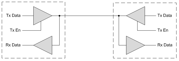
In a full-duplex system, there are two paths for sending data between two chips. There is a dedicated path from Chip 1 to Chip 2 and a separate dedicated path from Chip 2 to Chip 1. In a half-duplex system, there is only one path for sending data between two chips. Therefore the two chips must agree on whose turn it is to transmit. If the two try to transmit at the same time there will be collision on the line and the data will be lost.
In both figures above, the triangle shapes are your buffers. Note that in the half-duplex block diagram there is a signal Tx En. This is the signal that controls the tri-state transmit buffer. In the full-duplex block digram this signal is not required since both transmitters can be on 100% of the time without collision on the line.
Tri-State Buffers in FPGAs and ASICs
Below is the truth table for a tri-state buffer.
| Truth Table – Tri-State Buffer | ||
|---|---|---|
| Tx Data | Tx Enable | Output |
| 0 | 1 | 0 |
| 1 | 1 | 1 |
| X | 0 | Z (high impedance) |
Notice that if both Tx En are high at the same time, both transmitters will be driving and there will be a collision on the line. When using half-duplex tri-state buffers, it is critical that the modules sharing the line work out a communication scheme that avoids collision of data.
Inferring Tri-State Buffers in VHDL and Verilog
Tri-state buffers can be inferred by the synthesis tools. Here is how to infer a tri-state buffer in VHDL. The signal io_data is declared as inout in your port map section of your entity. In VHDL, ‘Z’ is high impedance.
inout io_data : std_logic; --port declaration of bidirectional data line

io_data   <= w_Tx_Data when w_Tx_En = '1' else 'Z';
w_Rx_Data <= io_data;
Here is how to infer a tri-state buffer in Verilog. The signal io_data is declared as inout in the port declaration section of your module. In Verilog, 1’bZ is high impedance.
inout io_data; //port declaration of bidirectional data line

assign io_data = Tx_En ? Tx_Data : 1'bZ;
assign Rx_Data = io_data;
Tri-State buffers are used frequently in circuits such as half-duplex UARTs and I2C interfaces. They are a very useful tool for digital designers to understand. You should know how to infer tri-state buffers in VHDL and Verilog.


Leave A Comment