Variables vs. Signals in VHDL
Variables and Signals in VHDL appears to be very similar. They can both be used to hold any type of data assigned to them. The most obvious difference is that variables use the := assignment symbol whereas signals use the <= assignment symbol. However the differences are more significant than this and must be clearly understood to know when to use which one. If you need a refresher, try this page about VHDL variables.
Signals vs. Variables:
- Variables can only be used inside processes, signals can be used inside or outside processes.
- Any variable that is created in one process cannot be used in another process, signals can be used in multiple processes though they can only be assigned in a single process.
- Variables need to be defined after the keyword process but before the keyword begin. Signals are defined in the architecture before the begin statement.
- Variables are assigned using the := assignment symbol. Signals are assigned using the <= assignment symbol.
- Variables that are assigned immediately take the value of the assignment. Signals depend on if it’s combinational or sequential code to know when the signal takes the value of the assignment.
The most important thing to understand (and the largest source of confusion) is that variables immediately take the value of their assignment, whereas signals depend on if the signal is used in combinational or sequential code. In combinational code, signals immediately take the value of their assignment. In sequential code, signals are used to create flip-flops, which inherently do not immediately take the value of their assignment. They take one clock cycle. In general, I would recommend that beginners avoid using variables. They can cause a lot of confusion and often are hard to synthesize by the tools.
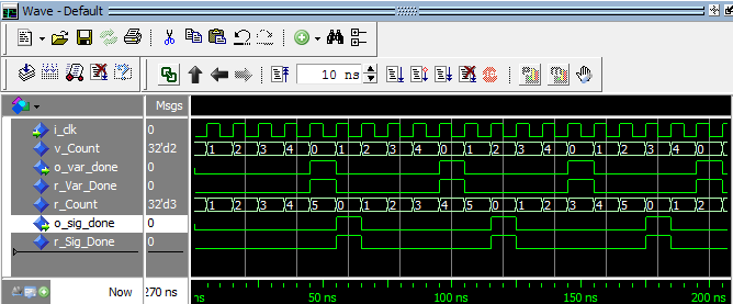
The example below demonstrates how signals behave differently than variables. Notice that r_Count and v_Count appear to be the same, but they actually behave very differently.
library ieee;
use ieee.std_logic_1164.all;
use ieee.numeric_std.all;

entity variable_vs_signal is
  port (
    i_clk   : in std_logic;
    o_var_done : out std_logic;
    o_sig_done : out std_logic
    );
end variable_vs_signal;

architecture rtl of variable_vs_signal is

  signal r_Var_Done : std_logic            := '0';
  signal r_Count    : natural range 0 to 6 := 0;
  signal r_Sig_Done : std_logic            := '0';

begin

  VAR_VS_SIG : process (i_clk)
    variable v_Count : natural range 0 to 5 := 0;
  begin
    if rising_edge(i_clk) then
      v_Count := v_Count + 1;           -- Variable
      r_Count <= r_Count + 1;           -- Signal

      -- Variable Checking
      if v_Count = 5 then
        r_Var_Done <= '1';
        v_Count := 0;
      else
        r_Var_Done <= '0';
      end if;

      -- Signal Checking
      if r_Count = 5 then
        r_Sig_Done <= '1';
        r_Count    <= 0;
      else
        r_Sig_Done <= '0';
      end if;

    end if;
  end process VAR_VS_SIG;

  o_var_done <= r_Var_Done;
  o_sig_done <= r_Sig_Done;

end rtl;
Testbench:
library ieee;
use ieee.std_logic_1164.all;
use ieee.numeric_std.all;

entity variable_vs_signal_tb is
end variable_vs_signal_tb;

architecture behave of variable_vs_signal_tb is

  constant c_CLK_PERIOD : time := 10 ns;

  signal r_Clock    : std_logic := '0';
  signal w_Var_Done : std_logic;
  signal w_Sig_Done : std_logic;

  component variable_vs_signal is
    port (
      i_clk      : in  std_logic;
      o_var_done : out std_logic;
      o_sig_done : out std_logic
      );
  end component variable_vs_signal;

begin

  r_Clock <= not r_Clock after c_CLK_PERIOD/2; variable_vs_signal_inst : variable_vs_signal port map ( i_clk => r_Clock,
      o_var_done => w_Var_Done,
      o_sig_done => w_Sig_Done
      );

end behave;
Variables can be a bit tricky to display in simulation. If you are using Modelsim, read more about how to see your variables in Modelsim’s waveform window. Look carefully at the waveform above. Do you see how o_var_done pulses every 5th clock cycle, but o_sig_done pulses every 6th clock cycle? Using signals and variables to store data generates very different behavior. Make sure you clearly understand what you code will be generating and make sure that you simulate your code to check that behaves like you want!


Leave A Comment