


Tutorial: Your First FPGA Program: An LED Blinker
Part 1: Design of VHDL or Verilog
This tutorial shows the construction of VHDL and Verilog code that blinks an LED at a specified frequency. Both VHDL and Verilog are shown, and you can choose which you want to learn first. Whenever design code is written the FPGA designer needs to ensure that it works the way that it was intended. Despite your best efforts, there will always be mistakes in your initial design. The best way to find these mistakes is in a simulation environment. This tutorial is broken up into 2 stages:
- Design of HDL
- Simulation of HDL
Both of these steps are crucial for successful FPGA development. Sometimes FPGA designers who are pressed for time will try to skip step two, the simulation of their code. However this is an extremely important step! Without proper simulation you will be forced to debug your code on hardware which can be a very difficult and time consuming endeavour.
Project Requirements:
Design HDL code that will blink an LED at a specified frequency of 100 Hz, 50 Hz, 10 Hz, or 1 Hz. For each of the blink frequencies, the LED will be set to 50% duty cycle (it will be on half the time). The LED frequency will be chosen via two switches which are inputs to the FPGA. There is an additional switch called LED_EN that needs to be ‘1’ to turn on the LED. The FPGA will be driven by a 25 MHz oscillator.
Let’s first draw the truth table for the frequency selector:
| Enable | Switch 1 | Switch 2 | LED Drive Frequency |
|---|---|---|---|
| 0 | – | – | (disabled) |
| 1 | 0 | 0 | 100 Hz |
| 1 | 0 | 1 | 50 Hz |
| 1 | 1 | 0 | 10 Hz |
| 1 | 1 | 1 | 1 Hz |
For this to work correctly there will be 4 inputs and 1 output. The signals will be:
| Signal Name | Direction | Description |
|---|---|---|
| i_clock | Input | 25 MHz Clock |
| i_enable | Input | The Enable Switch (Logic 0 = No LED Drive) |
| i_switch_1 | Input | Switch 1 in the Truth Table above |
| i_switch_2 | Input | Switch 2 in the Truth Table above |
| o_led_drive | Output | The signal that drives the LED |
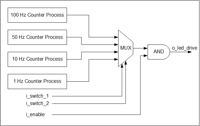
For the design there are four counter processes that run concurrently. This means that they are all running at the exact same time. Their job is to keep track of the number of clock pulses seen for each of the different frequencies. Even if the switches are not selecting that particular frequency, the counters are still running! This is the beauty of Hardware Design and concurrency. Everything runs all the time! It can be challenging to understand this initially, but it is the core concept that you need to master.
The switches only serve to select which output to use. They create what is known as a multiplexer. A multiplexer or mux for short is a selector that will select one of a number of inputs to propagate or pass to the output. It is a combinatorial piece of logic, meaning that it does not require a clock to operate. Below is a block diagram of the design. Spend some time thinking about how you might implement this design. Try writing the code yourself. The way that I chose to do can be found below.
VHDL code for the design, tutorial_led_blink.vhd:
library ieee;
use ieee.std_logic_1164.all;
use ieee.numeric_std.all;

entity tutorial_led_blink is
  port (
    i_clock      : in  std_logic;
    i_enable     : in  std_logic;
    i_switch_1   : in  std_logic;
    i_switch_2   : in  std_logic;
    o_led_drive  : out std_logic
    );
end tutorial_led_blink;

architecture rtl of tutorial_led_blink is

  -- Constants to create the frequencies needed:
  -- Formula is: (25 MHz / 100 Hz * 50% duty cycle)
  -- So for 100 Hz: 25,000,000 / 100 * 0.5 = 125,000
  constant c_CNT_100HZ : natural := 125000;
  constant c_CNT_50HZ  : natural := 250000;
  constant c_CNT_10HZ  : natural := 1250000;
  constant c_CNT_1HZ   : natural := 12500000;


  -- These signals will be the counters:
  signal r_CNT_100HZ : natural range 0 to c_CNT_100HZ;
  signal r_CNT_50HZ  : natural range 0 to c_CNT_50HZ;
  signal r_CNT_10HZ  : natural range 0 to c_CNT_10HZ;
  signal r_CNT_1HZ   : natural range 0 to c_CNT_1HZ;

  -- These signals will toggle at the frequencies needed:
  signal r_TOGGLE_100HZ : std_logic := '0';
  signal r_TOGGLE_50HZ  : std_logic := '0';
  signal r_TOGGLE_10HZ  : std_logic := '0';
  signal r_TOGGLE_1HZ   : std_logic := '0';

  -- One bit select wire.
  signal w_LED_SELECT : std_logic;

begin

  -- All processes toggle a specific signal at a different frequency.
  -- They all run continuously even if the switches are
  -- not selecting their particular output.

  p_100_HZ : process (i_clock) is
  begin
    if rising_edge(i_clock) then
      if r_CNT_100HZ = c_CNT_100HZ-1 then  -- -1, since counter starts at 0
        r_TOGGLE_100HZ <= not r_TOGGLE_100HZ;
        r_CNT_100HZ    <= 0;
      else
        r_CNT_100HZ <= r_CNT_100HZ + 1;
      end if;
    end if;
  end process p_100_HZ;


  p_50_HZ : process (i_clock) is
  begin
    if rising_edge(i_clock) then
      if r_CNT_50HZ = c_CNT_50HZ-1 then  -- -1, since counter starts at 0
        r_TOGGLE_50HZ <= not r_TOGGLE_50HZ;
        r_CNT_50HZ    <= 0;
      else
        r_CNT_50HZ <= r_CNT_50HZ + 1;
      end if;
    end if;
  end process p_50_HZ;


  p_10_HZ : process (i_clock) is
  begin
    if rising_edge(i_clock) then
      if r_CNT_10HZ = c_CNT_10HZ-1 then  -- -1, since counter starts at 0
        r_TOGGLE_10HZ <= not r_TOGGLE_10HZ;
        r_CNT_10HZ    <= 0;
      else
        r_CNT_10HZ <= r_CNT_10HZ + 1;
      end if;
    end if;
  end process p_10_HZ;


  p_1_HZ : process (i_clock) is
  begin
    if rising_edge(i_clock) then
      if r_CNT_1HZ = c_CNT_1HZ-1 then  -- -1, since counter starts at 0
        r_TOGGLE_1HZ <= not r_TOGGLE_1HZ;
        r_CNT_1HZ    <= 0;
      else
        r_CNT_1HZ <= r_CNT_1HZ + 1;
      end if;
    end if;
  end process p_1_HZ;


  -- Create a multiplexor based on switch inputs
  w_LED_SELECT <= r_TOGGLE_100HZ when (i_switch_1 = '0' and i_switch_2 = '0') else
                  r_TOGGLE_50HZ  when (i_switch_1 = '0' and i_switch_2 = '1') else
                  r_TOGGLE_10HZ  when (i_switch_1 = '1' and i_switch_2 = '0') else
                  r_TOGGLE_1HZ;


  -- Only allow o_led_drive to drive when i_enable is high (and gate).
  o_led_drive <= w_LED_SELECT and i_enable;

end rtl;
Verilog code for the design, tutorial_led_blink.v:
module tutorial_led_blink
  (
   i_clock,
   i_enable,
   i_switch_1,
   i_switch_2,
   o_led_drive
   );

  input i_clock;
  input i_enable;
  input i_switch_1;
  input i_switch_2;
  output o_led_drive;

  // Constants (parameters) to create the frequencies needed:
  // Input clock is 25 kHz, chosen arbitrarily.
  // Formula is: (25 kHz / 100 Hz * 50% duty cycle)
  // So for 100 Hz: 25,000 / 100 * 0.5 = 125
  parameter c_CNT_100HZ = 125;
  parameter c_CNT_50HZ  = 250;
  parameter c_CNT_10HZ  = 1250;
  parameter c_CNT_1HZ   = 12500;

  // These signals will be the counters:
  reg [31:0] r_CNT_100HZ = 0;
  reg [31:0] r_CNT_50HZ = 0;
  reg [31:0] r_CNT_10HZ = 0;
  reg [31:0] r_CNT_1HZ = 0;

  // These signals will toggle at the frequencies needed:
  reg 	     r_TOGGLE_100HZ = 1'b0;
  reg 	     r_TOGGLE_50HZ  = 1'b0;
  reg 	     r_TOGGLE_10HZ  = 1'b0;
  reg 	     r_TOGGLE_1HZ   = 1'b0;

  // One bit select
  reg 	     r_LED_SELECT;
  wire 	     w_LED_SELECT;


begin

  // All always blocks toggle a specific signal at a different frequency.
  // They all run continuously even if the switches are
  // not selecting their particular output.

  always @ (posedge i_clock)
    begin
      if (r_CNT_100HZ == c_CNT_100HZ-1) // -1, since counter starts at 0
        begin
          r_TOGGLE_100HZ <= !r_TOGGLE_100HZ;
          r_CNT_100HZ    <= 0;
        end
      else
        r_CNT_100HZ <= r_CNT_100HZ + 1;
    end


  always @ (posedge i_clock)
    begin
      if (r_CNT_50HZ == c_CNT_50HZ-1) // -1, since counter starts at 0
        begin
          r_TOGGLE_50HZ <= !r_TOGGLE_50HZ;
          r_CNT_50HZ    <= 0;
        end
      else
        r_CNT_50HZ <= r_CNT_50HZ + 1;
    end


  always @ (posedge i_clock)
    begin
      if (r_CNT_10HZ == c_CNT_10HZ-1) // -1, since counter starts at 0
        begin
          r_TOGGLE_10HZ <= !r_TOGGLE_10HZ;
          r_CNT_10HZ    <= 0;
        end
      else
        r_CNT_10HZ <= r_CNT_10HZ + 1;
    end


  always @ (posedge i_clock)
    begin
      if (r_CNT_1HZ == c_CNT_1HZ-1) // -1, since counter starts at 0
        begin
          r_TOGGLE_1HZ <= !r_TOGGLE_1HZ;
          r_CNT_1HZ    <= 0;
        end
      else
        r_CNT_1HZ <= r_CNT_1HZ + 1;
    end

  // Create a multiplexer based on switch inputs
  always @ (*)
  begin
    case ({i_switch_1, i_switch_2}) // Concatenation Operator { }
      2'b11 : r_LED_SELECT <= r_TOGGLE_1HZ;
      2'b10 : r_LED_SELECT <= r_TOGGLE_10HZ;
      2'b01 : r_LED_SELECT <= r_TOGGLE_50HZ;
      2'b00 : r_LED_SELECT <= r_TOGGLE_100HZ;
    endcase
  end

  assign o_led_drive = r_LED_SELECT & i_enable;

  // Alternative way to design multiplexer (same as above):
  // More compact, but harder to read, especially to those new to Verilog
  // assign w_LED_SELECT = i_switch_1 ? (i_switch_2 ? r_TOGGLE_1HZ : r_TOGGLE_10HZ) :
                                        (i_switch_2 ? r_TOGGLE_50HZ : r_TOGGLE_100HZ);
  // assign o_led_drive = w_LED_SELECT & i_enable;


end

endmodule

Leave A Comment